dimensioning sheet metal Reading a sheet metal drawing involves identifying the details of the design of sheet metal parts, such as dimensions, geometry, material specifications, and any special requirements. Meanwhile, detailing this . Located in the Archdale, North Carolina, US Metal Crafters offers a wide variety of contract manufacturing & metal fabrication services. Laser Cutting Capacity Available, Call us at (336) 490-5397 today for more details.
0 · simple sheet metal drawings
1 · sheet metal part drawing
2 · sheet metal layout drawings
3 · sheet metal drawing symbols
4 · sheet metal drawing dimensioning
5 · sheet metal dimensioning standards
6 · sheet metal dimensioning guidelines
7 · sheet metal detail drawing
12 Pack 4 Inch Ultra-Thin LED Recessed Ceiling Light with Junction Box,5000K Clear White,9W Eqv,80W Canless Wafer Slim Panel Downlight,led recessed Lighting Lights (5000K, 4 Inch) - Amazon.com . Tamper Resistant 15 Amp Standard Electrical Wall Outlet, Residential Grade, Self-grounding, 125V, 2 Pole 3 Wire, 5-15R, UL Listed, Glossy Black, 10 .
Some critical dimensions that need to be considered when setting up sheet metal in CAD software are sheet metal thickness, the k-factor, and bend radius. One needs to check that these factors are consistent with the tooling that will be .A fully dimensioned sheet metal drawing includes dimensions for all bends, holes, countersinks, flanges, and other formed features (such as hems and curls, ribs, dimples, etc.). It is a best .Sheet metal fabrication is the process of forming parts from a metal sheet by punching, cutting, stamping, and bending. 3D CAD files are converted into machine code, which controls a .
Sheet metal design guidelines are followed for sheet metal enclosure and part design to ensure the first time right product and reduce cost.
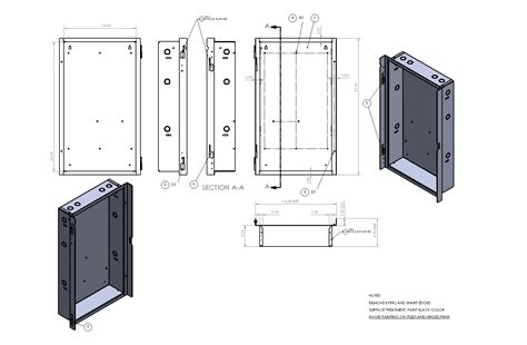
Reading a sheet metal drawing involves identifying the details of the design of sheet metal parts, such as dimensions, geometry, material specifications, and any special requirements. Meanwhile, detailing this . Sheet metal drawings are a type of mechanical drawing primarily used to depict the details and dimensional specifications of sheet metal fabrication parts. They provide detailed descriptions of the part’s shape, . Part sketches should be dimensioned and constrained in a manner that allows them to be easily modified without deforming the part and causing rebuild errors. Design intent .
Sheet metal detail drawings developed using CAD tools like SolidWorks, Inventor®, SolidEdge, Creo etc. abide by design rules and enable seamless collaboration. They also address the need for standard methods of .In CAD drafting for sheet metal fabrication, dimensioning involves precisely annotating the size and location of features on 2D drawings or 3D models, crucial for part fit and function. This .Dimension the part in a single direction wherever possible. Because of the sequential nature of the forming process, and the fact that dimensional variation is introduced at each bend, dimensioning in a single direction parallels the process and helps to .Some critical dimensions that need to be considered when setting up sheet metal in CAD software are sheet metal thickness, the k-factor, and bend radius. One needs to check that these factors are consistent with the tooling that will be used in manufacturing.
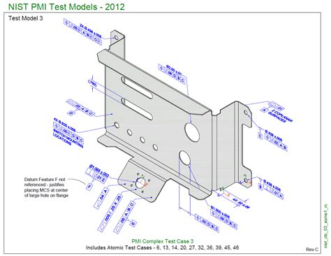
A fully dimensioned sheet metal drawing includes dimensions for all bends, holes, countersinks, flanges, and other formed features (such as hems and curls, ribs, dimples, etc.). It is a best practice to dimension to virtual intersection points and show included bend angles.
simple sheet metal drawings

Sheet metal fabrication is the process of forming parts from a metal sheet by punching, cutting, stamping, and bending. 3D CAD files are converted into machine code, which controls a machine to precisely cut a flat pattern, which can be formed .Sheet metal design guidelines are followed for sheet metal enclosure and part design to ensure the first time right product and reduce cost.
antique westinghouse drawbridge electric switch box
Reading a sheet metal drawing involves identifying the details of the design of sheet metal parts, such as dimensions, geometry, material specifications, and any special requirements. Meanwhile, detailing this information requires a series of . Sheet metal drawings are a type of mechanical drawing primarily used to depict the details and dimensional specifications of sheet metal fabrication parts. They provide detailed descriptions of the part’s shape, dimensions, material, surface treatments, allowable tolerances, and other pertinent information. Part sketches should be dimensioned and constrained in a manner that allows them to be easily modified without deforming the part and causing rebuild errors. Design intent should be considered when creating part sketches.
Sheet metal detail drawings developed using CAD tools like SolidWorks, Inventor®, SolidEdge, Creo etc. abide by design rules and enable seamless collaboration. They also address the need for standard methods of dimensioning by following the rules of region-specific and universal drafting practices. 1. Need for detailing as per design consideration.In CAD drafting for sheet metal fabrication, dimensioning involves precisely annotating the size and location of features on 2D drawings or 3D models, crucial for part fit and function. This includes specifying all necessary measurements like length, width, depth, and radius to match the physical component sizes.Dimension the part in a single direction wherever possible. Because of the sequential nature of the forming process, and the fact that dimensional variation is introduced at each bend, dimensioning in a single direction parallels the process and helps to .
sheet metal part drawing
Some critical dimensions that need to be considered when setting up sheet metal in CAD software are sheet metal thickness, the k-factor, and bend radius. One needs to check that these factors are consistent with the tooling that will be used in manufacturing.A fully dimensioned sheet metal drawing includes dimensions for all bends, holes, countersinks, flanges, and other formed features (such as hems and curls, ribs, dimples, etc.). It is a best practice to dimension to virtual intersection points and show included bend angles.
Sheet metal fabrication is the process of forming parts from a metal sheet by punching, cutting, stamping, and bending. 3D CAD files are converted into machine code, which controls a machine to precisely cut a flat pattern, which can be formed .Sheet metal design guidelines are followed for sheet metal enclosure and part design to ensure the first time right product and reduce cost.
Reading a sheet metal drawing involves identifying the details of the design of sheet metal parts, such as dimensions, geometry, material specifications, and any special requirements. Meanwhile, detailing this information requires a series of .
Sheet metal drawings are a type of mechanical drawing primarily used to depict the details and dimensional specifications of sheet metal fabrication parts. They provide detailed descriptions of the part’s shape, dimensions, material, surface treatments, allowable tolerances, and other pertinent information. Part sketches should be dimensioned and constrained in a manner that allows them to be easily modified without deforming the part and causing rebuild errors. Design intent should be considered when creating part sketches.

Sheet metal detail drawings developed using CAD tools like SolidWorks, Inventor®, SolidEdge, Creo etc. abide by design rules and enable seamless collaboration. They also address the need for standard methods of dimensioning by following the rules of region-specific and universal drafting practices. 1. Need for detailing as per design consideration.
sheet metal layout drawings


aop metal fabricators
anya hindmarch marano metallic glitter-finished box clutch
Ultimate Sheet Metal, LLC located at 835 N Cypress St, Orange, TX 92867 - reviews, ratings, hours, phone number, directions, and more.
dimensioning sheet metal|sheet metal drawing dimensioning