bend relief sheet metal Learn how to design sheet metal parts with bend relief, small holes, hole distortion, and minimum flange widths. The article explains the benefits and constraints of different bending methods and materials.
Top 10 Best Metal Fabricators in Nashville, TN - July 2024 - Yelp - Duck Welding Sales & Service, ACI Supply, Steel Beautiful Welding and Fabrication, Iconic Metal Works, Modern Iron Concepts, Tennessee Tool Works, B&B Custom Welding, Lucas Industrial, Legion Metal & Speed Shop, Gladeville Welding and Fabrication
0 · solidworks sheet metal relief cut
1 · solidworks sheet metal corner relief
2 · solidworks sheet metal bend relief
3 · sheet metal fabrication design guide
4 · sheet metal corner relief chart
5 · sheet metal bending chart
6 · sheet metal bend relief guidelines
7 · auto relief solidworks sheet metal
Shop Welding and Metal Fabrication: 1st Edition at MSC Direct top provider of high quality products
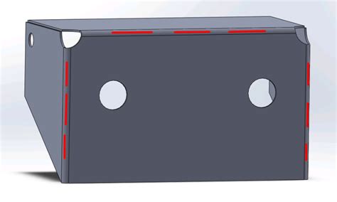
A bend relief prevents tears from occurring where there is a transition between bends or between a bend and a flat surface. They are a .Bend relief is provided at the end of the bending edge in sheet metal design to avoid any crack tearing in the corner. Recommended Bend Relief height is always more than two times of .Bend Relief - When a bend is made close to an edge the material may tear unless bend relief is given. Figure "A" shows a torn part. Figure "B" shows a part with the edge a sufficient distance . Bend reliefs are two small cuts made in a piece of sheet metal to free up the metal between them. Although they are small features, leaving .
In this comprehensive guide, we’ll explore the intricate world of sheet metal bend relief guidelines, uncovering advanced techniques and real-world applications that contribute to successful fabrication endeavors. Learn how to design sheet metal parts with bend relief, small holes, hole distortion, and minimum flange widths. The article explains the benefits and constraints of different bending methods and materials.
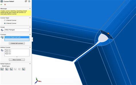
Bend reliefs prevent tears during transitions between bends or between a bend and a flat surface. They ensure a clean part free from deformation, burrs, and sharp points, especially crucial for parts subject to .CUT/BEND RELIEF DESIGN TIPS • To ensure cost-effective production, design cut and bend reliefs with a minimum of 2.5x material thickness. • For prototype and short-run quantities, the . A bend relief creates space between the bent and unbent surfaces so that the edge of the sheet metal is perpendicular to the bend itself. The gap between the bend and surrounding material allows us to shape the sheet in . See how and when specifically to design bend reliefs and corner reliefs in sheet metal parts to open up geometry options & tighter tolerances
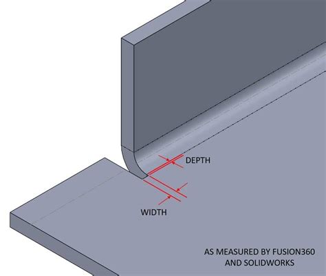
A bend relief prevents tears from occurring where there is a transition between bends or between a bend and a flat surface. They are a great way to ensure a clean looking part that is free from deformation, burrs, and sharp points where the bend edges terminate.Bend relief is provided at the end of the bending edge in sheet metal design to avoid any crack tearing in the corner. Recommended Bend Relief height is always more than two times of sheet thickness plus bend radius. Creating an extruded hole .Bend Relief - When a bend is made close to an edge the material may tear unless bend relief is given. Figure "A" shows a torn part. Figure "B" shows a part with the edge a sufficient distance from the form. This distance should never be less than the radius of the bend.Bend reliefs are two small cuts made in a piece of sheet metal to free up the metal between them. Although they are small features, leaving them out can cause stress to concentrate at the bend line, resulting in deformed holes and slots.
In this comprehensive guide, we’ll explore the intricate world of sheet metal bend relief guidelines, uncovering advanced techniques and real-world applications that contribute to successful fabrication endeavors.
solidworks sheet metal relief cut

solidworks sheet metal corner relief
The article discusses making small holes and when to use a punch or laser cutter, inside radius measurements and how they differ depending on whether you are coining or air bending on a press brake, and adding bend relief to prevent tearing material. Bend reliefs prevent tears during transitions between bends or between a bend and a flat surface. They ensure a clean part free from deformation, burrs, and sharp points, especially crucial for parts subject to vibration or flexion.

CUT/BEND RELIEF DESIGN TIPS • To ensure cost-effective production, design cut and bend reliefs with a minimum of 2.5x material thickness. • For prototype and short-run quantities, the minimum cut relief can be a laser or water jet cut kerf (0.010” - 0.040”). • Lanced (sheared) features with zero cut relief are possible but
A bend relief creates space between the bent and unbent surfaces so that the edge of the sheet metal is perpendicular to the bend itself. The gap between the bend and surrounding material allows us to shape the sheet in the press brake cleanly, eliminating cracking and tearing. See how and when specifically to design bend reliefs and corner reliefs in sheet metal parts to open up geometry options & tighter tolerances A bend relief prevents tears from occurring where there is a transition between bends or between a bend and a flat surface. They are a great way to ensure a clean looking part that is free from deformation, burrs, and sharp points where the bend edges terminate.
Bend relief is provided at the end of the bending edge in sheet metal design to avoid any crack tearing in the corner. Recommended Bend Relief height is always more than two times of sheet thickness plus bend radius. Creating an extruded hole .Bend Relief - When a bend is made close to an edge the material may tear unless bend relief is given. Figure "A" shows a torn part. Figure "B" shows a part with the edge a sufficient distance from the form. This distance should never be less than the radius of the bend.Bend reliefs are two small cuts made in a piece of sheet metal to free up the metal between them. Although they are small features, leaving them out can cause stress to concentrate at the bend line, resulting in deformed holes and slots.
In this comprehensive guide, we’ll explore the intricate world of sheet metal bend relief guidelines, uncovering advanced techniques and real-world applications that contribute to successful fabrication endeavors. The article discusses making small holes and when to use a punch or laser cutter, inside radius measurements and how they differ depending on whether you are coining or air bending on a press brake, and adding bend relief to prevent tearing material. Bend reliefs prevent tears during transitions between bends or between a bend and a flat surface. They ensure a clean part free from deformation, burrs, and sharp points, especially crucial for parts subject to vibration or flexion.
CUT/BEND RELIEF DESIGN TIPS • To ensure cost-effective production, design cut and bend reliefs with a minimum of 2.5x material thickness. • For prototype and short-run quantities, the minimum cut relief can be a laser or water jet cut kerf (0.010” - 0.040”). • Lanced (sheared) features with zero cut relief are possible but

solidworks sheet metal bend relief

electrical transformer box in fire escape
For over 70 years, Welded Sheet Metal Specialty Co.'s mission is to provide our customers with a product they are proud to put their name on. 745 Greenway Dr, Pittsburgh, Pennsylvania, .
bend relief sheet metal|sheet metal bend relief guidelines