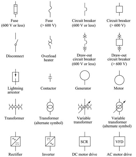
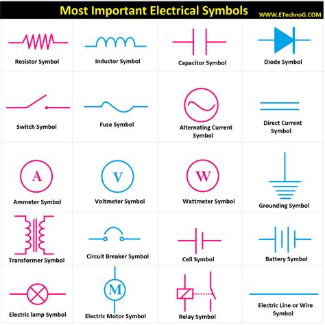
box with diagonal line electrical symbol Electrical symbols are the most commonly used symbols in circuit diagramming. Amplifiers (denoted by triangle shapes) increase the output signal in your circuit. Capacitors (parallel lines) store energy in your system, while resistors (zigzag . Auto body professionals welding sheet metal together will usually do it using one of three processes: spot welding, MIG (metal inert gas) welding, and TIG (tungsten inert gas) welding. Spot welding, or resistance welding, is where .
0 · single line diagram symbols
1 · electrical symbols and diagrams
2 · electrical line diagram examples
3 · electrical line diagram
4 · electrical control line diagram
5 · electrical circuit diagram symbols
6 · decoding wiring diagram symbol
7 · decoding electrical symbols
I'm setup for both and used both with different guns (M15 and M25 setups on a MM210 welder). I've pretty much settled in with Lincoln's L56 .030" wire for everything, including sheetmetal. Like Hankj says, its more technique than wire size when it comes to sheetmetal.
In an electrical single line diagram, each symbol represents a specific electrical component or device. For example, a circle with a horizontal line through it represents a transformer, while a rectangle with a diagonal line through it .8. Fuse Symbol: The fuse symbol is represented by a small box with a diagonal line through it. It represents an electrical safety device that protects a circuit from overcurrent. The current rating of the fuse is usually indicated next to or inside . I'd like to ask about this "empty set" like symbol with a diagonal line through a circle, as shown in the picture below. I have found it in an old electrical schematic. What is it exactly?Relays: Relays play a crucial role in controlling larger electrical devices or systems. Relay symbols in industrial wiring diagrams consist of a rectangular box with one or more diagonal lines inside, representing the relay contacts and .
Electrical symbols are the most commonly used symbols in circuit diagramming. Amplifiers (denoted by triangle shapes) increase the output signal in your circuit. Capacitors (parallel lines) store energy in your system, while resistors (zigzag .The most common resistor symbols include a zigzag line and a rectangle with a diagonal line. These symbols indicate the presence of resistance in a circuit, which limits the flow of electrical current.Learn about the different symbols used in line diagrams to represent various electrical and mechanical components. Understand the meaning and function of these symbols in order to effectively interpret and create line diagrams for .Understanding electrical schematic symbols is essential for anyone involved in the design, construction, or maintenance of electrical systems. These symbols represent different types of electrical components such as resistors, .
One of the key components in a residential electrical diagram is the main electrical service symbol. This symbol typically represents the main circuit breaker panel or fuse box, where electricity is distributed throughout the house.One-line diagram – a diagram that uses single lines and graphic symbols to indicate the path and components of an electrical circuit. One-line diagrams are used when information about a circuit is required but detail of the actual wire connections and operation of the circuit are not.In an electrical single line diagram, each symbol represents a specific electrical component or device. For example, a circle with a horizontal line through it represents a transformer, while a rectangle with a diagonal line through it represents a circuit breaker.
8. Fuse Symbol: The fuse symbol is represented by a small box with a diagonal line through it. It represents an electrical safety device that protects a circuit from overcurrent. The current rating of the fuse is usually indicated next to or inside the symbol. 9. Relay Symbol: The relay symbol is represented by a rectangle with a diagonal line . I'd like to ask about this "empty set" like symbol with a diagonal line through a circle, as shown in the picture below. I have found it in an old electrical schematic. What is it exactly?Relays: Relays play a crucial role in controlling larger electrical devices or systems. Relay symbols in industrial wiring diagrams consist of a rectangular box with one or more diagonal lines inside, representing the relay contacts and their connection points.
Electrical symbols are the most commonly used symbols in circuit diagramming. Amplifiers (denoted by triangle shapes) increase the output signal in your circuit. Capacitors (parallel lines) store energy in your system, while resistors (zigzag lines) reduce current flow.The most common resistor symbols include a zigzag line and a rectangle with a diagonal line. These symbols indicate the presence of resistance in a circuit, which limits the flow of electrical current.Learn about the different symbols used in line diagrams to represent various electrical and mechanical components. Understand the meaning and function of these symbols in order to effectively interpret and create line diagrams for engineering and technical purposes.Understanding electrical schematic symbols is essential for anyone involved in the design, construction, or maintenance of electrical systems. These symbols represent different types of electrical components such as resistors, capacitors, transformers, switches, and many more.

single line diagram symbols
One of the key components in a residential electrical diagram is the main electrical service symbol. This symbol typically represents the main circuit breaker panel or fuse box, where electricity is distributed throughout the house.One-line diagram – a diagram that uses single lines and graphic symbols to indicate the path and components of an electrical circuit. One-line diagrams are used when information about a circuit is required but detail of the actual wire connections and operation of the circuit are not.In an electrical single line diagram, each symbol represents a specific electrical component or device. For example, a circle with a horizontal line through it represents a transformer, while a rectangle with a diagonal line through it represents a circuit breaker.8. Fuse Symbol: The fuse symbol is represented by a small box with a diagonal line through it. It represents an electrical safety device that protects a circuit from overcurrent. The current rating of the fuse is usually indicated next to or inside the symbol. 9. Relay Symbol: The relay symbol is represented by a rectangle with a diagonal line .
I'd like to ask about this "empty set" like symbol with a diagonal line through a circle, as shown in the picture below. I have found it in an old electrical schematic. What is it exactly?
Relays: Relays play a crucial role in controlling larger electrical devices or systems. Relay symbols in industrial wiring diagrams consist of a rectangular box with one or more diagonal lines inside, representing the relay contacts and their connection points.
Electrical symbols are the most commonly used symbols in circuit diagramming. Amplifiers (denoted by triangle shapes) increase the output signal in your circuit. Capacitors (parallel lines) store energy in your system, while resistors (zigzag lines) reduce current flow.The most common resistor symbols include a zigzag line and a rectangle with a diagonal line. These symbols indicate the presence of resistance in a circuit, which limits the flow of electrical current.
Learn about the different symbols used in line diagrams to represent various electrical and mechanical components. Understand the meaning and function of these symbols in order to effectively interpret and create line diagrams for engineering and technical purposes.Understanding electrical schematic symbols is essential for anyone involved in the design, construction, or maintenance of electrical systems. These symbols represent different types of electrical components such as resistors, capacitors, transformers, switches, and many more.


ngt codan handset junction box

electrical symbols and diagrams
I use both in my Linclone mig, and the .030 in my cold wire feeder for tig work. You can planish it pretty good, or just grind it off. And yes it is easy to grind if you use Argon75/25Co2.
box with diagonal line electrical symbol|electrical symbols and diagrams